Introduction
A Voice Tracking system acts as the link between the microphone system and the cameras. The microphones detect where sound is coming from and send this positional information to the Voice Tracker (VT). The VT then converts it into camera control commands and manages the automatic switching of the video output.
We have introduced several improvements to enhance smoothness and reliability, making the system suitable for a wide range of environments, including meeting rooms, classrooms, and presentation spaces of various sizes and layouts.
Getting Started
This article provides step-by-step guidance to correctly install and configure the CamDirector® Voice Tracker system, including the CD600 (previously CD500), connected PTZ cameras, and compatible ceiling microphones.
- Ensure the CD600 and all PTZ cameras are powered on.
- Assign IP addresses to all devices within the same network range /subnet.
- Configure each camera in its own web interface before configuring them in the Voice Tracker software.
- Physically install all cameras and microphones in the room before setting up their locations in the room layout.
- When adding objects in the software, measure all X, Y, and Z coordinates from a fixed room reference point, accurate to 1 cm.
Set up the CD600
See the Quick Guide of the CD600.
Set up the Cameras
See the Quick Guide of the cameras.
Configure the Cameras
Ensure all cameras and the CD600 have an IP address in the same subnet. In Voice Tracker, you can only use one camera model. Once you’ve selected a model, the others will no longer be selectable. Log in to each camera’s web interface. Set up the cameras as specified in the configuration requirements when adding them to the room layout. The camera settings are different for the CD500 and the CD600, pay attention to what the webinterface of the Voice Tracker displays.
For the CD600 the camera streaming settings look like this:
Configure the Microphones
Room Reference Point
Start by defining a fixed reference point (e.g. the top-left corner of the room). All measurements will be taken from this 0,0,0 point.
Adding Objects
When the room size is configured, the first step is to add objects, like tables, chairs and zones. These are for easy recognition of the room and where audio sources are located.
Adding Microphones
The next step is to add a microphone. Select the brand and model, assign a name, and enter the X, Y, Z coordinates from the reference point. Also set the orientation, this is sometimes difficult to make out. Take note that it might be necessary to make changes if the sound appears to be coming from the wrong direction.
Demonstration Microphone (CD600 only)
To make it easy to give a demonstration to (potential) customers, a demo microphone is built into the system. When you simply add this demo microphone to the configuration, it will automatically simulate sound coming from your objects. The Voice Tracking system then uses those locations to control the cameras, so the cameras will automatically move to the corresponding seats and or zones. This allows you to demonstrate how the system works in a quick and low-effort way, without needing any real microphones or active speakers. Ideal for demos, presentations, and first introductions to Voice Tracking.
Bosch Dicentis (CD600 only)
In the background, the Voice Tracker system keeps track of how long each speaker is talking and how long they are not talking, and assigns a ranking. There is also an option to integrate the Bosch DICENTIS conference system. What basically happens is this: when a participant presses the button on a discussion post, their ranking immediately jumps to maximum, so the output is switched to that person right away.
Here you can enter the IP settings and the username/password, and configure the seats.

Shure MXA920
Access the web interface and go to Settings > Network to set Control and Dante IP addresses. Use the Control IP for Voice Tracker integration. Check the Services page for required port numbers.

Yamaha RM-CG
Log into the web GUI and navigate to Settings > Network to configure the required IP settings.

Audio-Technica ATND1061DAN
Access the web interface, go to System Settings > Network. Use the Control IP. Default ports are 17000 and 17300.

Sennheiser TeamConnect Ceiling 2 / Medium
Use the Sennheiser Control Cockpit software. Select the microphone, open its settings, and go to the network tab. The TCCM requires an API password.

Configure the Voice Tracker
Room Size
Select Room Configuration under the Objects tab. Enter the room dimensions. The shape does not need to be exact but must include the full usable space.
Add Objects
Place all microphones, cameras, chairs, tables, and zones in the layout. Each object is positioned relative to the (0,0,0) reference point. Set orientation where applicable.
Check Device Settings
Under the Devices tab, verify that no devices show warning icons and all devices are correctly recognized.
Choose Scenario
Go to the Switcher tab and select the automatic scenario. Alternatively, create a custom scenario using manual presets and flows.
Turn On
Click the Live button in the top menu bar. The system will activate and begin live camera switching based on audio location. The orange screen disappears, and the camera video comes through via the HDMI stream.
Manual Configuration
Set Up Presets
In the Presets tab, configure specific camera positions. Name the preset, select a camera, adjust its position, and save.
Configure Flows
In the Flows tab, assign presets to seats or zones. Create a flow by defining a trigger and linking it to a preset.
Set Up Scenarios
Go to the Scenario tab to manage different sets of flows. By default, all flows are active. Use scenarios for different room uses.
Activate Switcher
Open the Switcher tab and activate the system. Select the scenario that matches the use case.
Important Information
Because of the high likeliness for the Voice Tracker to be used in conjunction with video conferencing software, it is important to switch off all autoframing and 'beautify' options in that software. For example, in Google Meet this option is called 'framing' in the appearance tab.
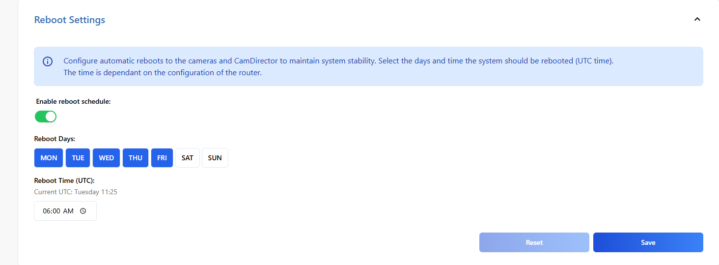
Reboot Options
Avonic recommends switching the Voice Tracker on when it is in use and turning it off when it is not needed. For installations where the CamDirector and connected cameras operate continuously, we advise scheduling a daily reboot. At the chosen time of reboot, the CamDirector will first reboot the cameras and after 2 minutes, itself. Take note that the CamDirector time is in UTC. If the days are blue, they are active.
Director Settings
In Settings, click the three dots in the top-right corner. Under Director Settings, you will find several items you can adjust. The blue information boxes provide a short explanation for each setting, but I’d like to highlight a few of them:
Silence Threshold:
This allows you to set the time after which the Voice Tracker switches back to the overview camera. Please note that the overview preset must be configured in the Scenarios.
Switch to primary camera when available:
In the Flow configuration, you select two presets and define which preset should be used as the primary option. If that preset is not available, the Voice Tracker will use the secondary preset. If the Voice Tracker switches to the second option, it can continue to check in the background whether the primary preset becomes available again, and then switch back to it when possible.
Save bandwidth for MJPEG stream (cd600 only):
The both MJPEG settings can be useful if you have limited network bandwidth.